Abstract. Building a robot requires careful selection of components that interact across networks while meeting timing deadlines. Given the complexity associated, as robots get damaged or security compromised, their components will increasingly require updates and replacements. Contrary to the expectations and similar to Ford in the 1920s with cars, most robot manufacturers oppose to this. They employ planned obsolescence practices organizing dealers and system integrators into “private networks”, providing repair parts only to “certified” companies to discourage repairs and evade competition. In this article we introduce and advocate for robot teardown as an approach to study robot hardware architectures and fuel security research. We show how teardown can help understanding the underlying hardware and demonstrate how our approach can help researchers uncovering security vulnerabilities. Our case studies show how robot teardown becomes an essential practice to security in robotics, helping us identify and report a total of 100 security flaws with 17 new CVE IDs over a period of two years. Lastly, we finalize by demonstrating how, through teardown, planned obsolescence hardware limitations can be identified and bypassed obtaining full control of the hardware, which poses both a threat to the robot manufacturers’ business model as well as a security threat.
Full text transcribed from the original publication source.
1Notes for Practice
- Following a red teaming methodology, we discuss the empirical results of three robot teardowns performed on popular industrial collaborative robots and uncover various quality and safety flaws in the process.
- We gain repairing capabilities in the robots which leads us to acquire means to mitigate security flaws early by simply extending the robotic system with off-the-shelf additional hardware elements.
- We show how robot teardown helps pinpoint security vulnerabilities across internal and external robot networks while discussing some of them.
- We show evidence of planned obsolescence practices in robotics on leading industrial collaborative robots and demonstrate how by applying minor fixes, we managed to bypass the obsolescence limitations.
Keywords: Teardown, robotics, security, repair, safety
21. Introduction
Robotics is the art of system integration (Mayoral-Vilches et al., 2017)
Building a robot requires one to carefully select components that exchange information across networks while meeting timing deadlines. In a way, a robot is a network of networks. One that comprises sensors to “read” the world, actuators to produce a physical change, and dedicated computational resources to process it all and respond coherently, in time, and according to its application. Roboticists often conceive the robot not as one of its parts, but as the complete system including all of its components, whether they are assembled under the same structure or physically distributed. In the case of a robotic manipulator, these robots are often presented physically distributed and include the robot arm mechanics (which generally include actuators and sensors), the human-machine interface (HMI) or teach pendant, the controller (the main compute substrate for reasoning), and any additional safety mechanism related to the robot operation. The robotic system is thereby the composition of all these sub-systems and networks.
Under such system integration complexity, it is not uncommon for one of the robot sub-components to fail over time, often leading to the complete system malfunction. Given the high price point of robots, it is reasonable to consider the need for repairing these machines, often replacing individual faulty components for continued operation, or simply for re-purposing them. The European Commission (EC) showed early interest on this topic in a 2019 report evaluating different scoring systems for repairing and upgrading different consumer-oriented products
- Making items difficult to repair (by raising the cost of repair, requiring special tools, etc.).
- Failing to provide information (for instance, manuals are not provided).
- Systematic obsolescence (making parts among models incompatible or making it impossible to fix newer models with parts from the older models).
- Numbering (frequently changing the model numbers to make it psychologically less attractive to use old models).
- Legal approaches (prohibiting access and modification to the internal structure of products by means of copyrights and patents).
Similar to Ford in the 1920s
Cybersecurity in robotics is still on its early stages
The present article introduces and promotes robot teardown as a systematic process to repair robots, improve robot hardware and research its security. We advocate against the business priorities set in industry to avoid repairs and planned obsolescence. Instead, we advocate for a Right to Repair in robotics as a means to reduce robot e-waste and recycle components, both across robots and throughout use-cases. Ultimately, we argue that, in the long run, the more researchers and practitioners will get used to systematically teardown robots, the more this practice will impact the quality assurance of hardware in robotics, putting pressure on manufacturers to produce robots with better hardware security measures, thereby safer.
Our contributions are fourfold: first, we discuss the empirical results of three robot teardowns performed on popular industrial collaborative robots and uncover various quality and safety flaws in the process. Second, we demonstrate how as a result of the teardown, we gain repairing capabilities in the robots. This leads us to acquire means to mitigate security flaws early by simply extending the robotic system with off-the-shelf additional hardware elements that increase the overall cybersecurity posture with a minimal cost impact. Third, we show how teardown helps pinpoint security vulnerabilities across internal and external robot networks while discussing some of them. Fourth, we show evidence of planned obsolescence practices in robotics on leading industrial collaborative robots and demonstrate how by applying minor fixes, we managed to bypass the obsolescence limitations obtaining full control of the hardware across subsequent releases.
The content below is organized as follows: Section 2 describes the robot teardown process in three different robots and Section 3 the posterior reversing exercise to gain repairing capabilities. Section 4 argues about the obsolescence indicators encountered and demonstrates how to bypass them as a result of the results in previous sections. Finally, Section 5 summarizes our work and draws some conclusions.
32. Robot teardown
A teardown is the process of taking apart a product to understand how it is made and works. More formally, it is the approach to modeling the functional behavior and physical components of a product
The motivation behind teardowns was previously researched by other groups
Based on common teardown practices
3.12.1 Case Study 1: Teardown of an industrial collaborative robot
Figure 2 shows a selection of images obtained from the complete teardown of the UR3 CB3.1 industrial collaborative robot. Our goal is to show how a systematic teardown can lead to understanding how to obtain repairing capabilities of the complete robot, including the controller (i.e., the “brain” of the robot), teach pendant, and robot arm mechanics. We put particular emphasis in the CB3.1 controller since most safety-related electronics reside in there.
An interesting observation is depicted in Figure 2F, which displays that the compute substrate in charge of implementing the safety logic is the NXP LPC4437JET256 microcontroller. While doing hardware reconnaissance we found the following excerpt within the part datasheet of the corresponding microcontroller.
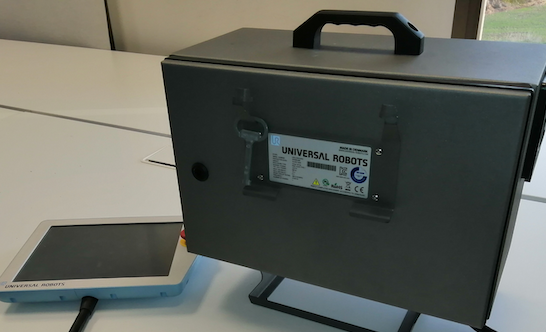
A) Universal Robots UR3 robot CB3.1 controller and associated teach pendant (HMI). The controller has a mechanical lock aimed to secure physical access.
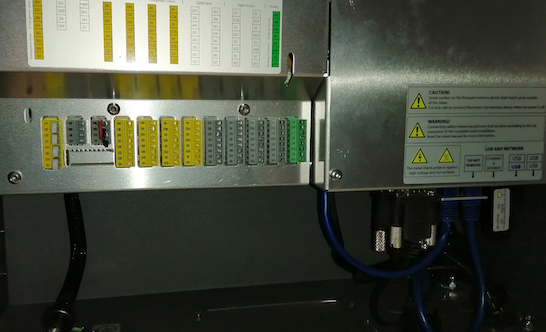
B) Inside the controller we learn about connectors and cables, which are exposed. The left side includes I/O and safety, whereas the right one leads to the main computer.
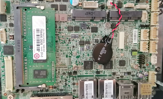
C) The main computer of the controller with a 2G DDR3L RAM module from Transcend. Ethernet NICs are connected to automotive-grade controllers from Intel.
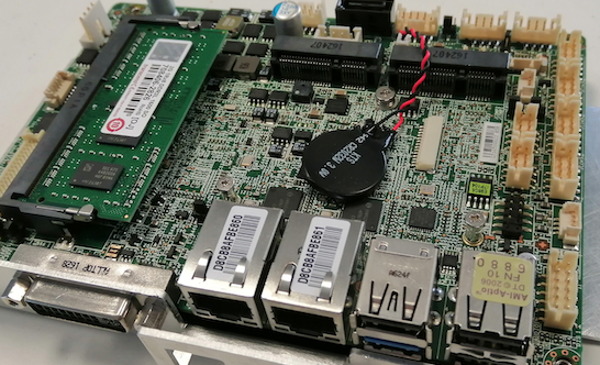
D) No secondary memory is located on the printed circuit board (PCB) besides minor non-volatile memories and the USB stick we found connected outside.
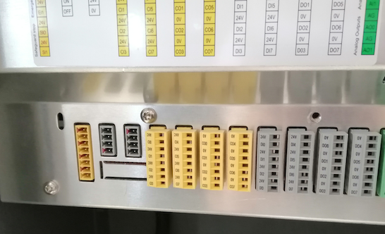
E) The safety side of the controller (documented in the user manuals) includes quick connectors which can be removed by carefully wiggling them out.
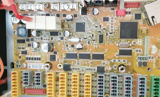
F) After removing the metal shields, the safety board electronics are fully visible. The main logic is driven by an NXP LPC4437JET256 microcontroller unit (MCU).
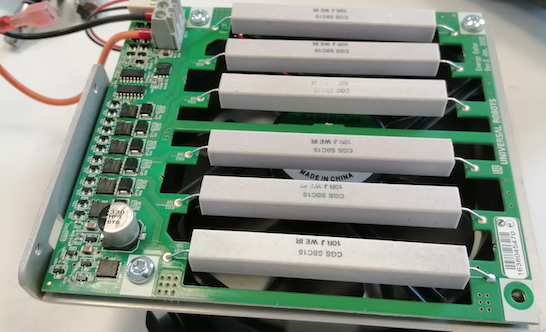
G) The energy-eater board. This component tends to overheat a fair bit and should generally be checked in case of failure for signs of degradation.
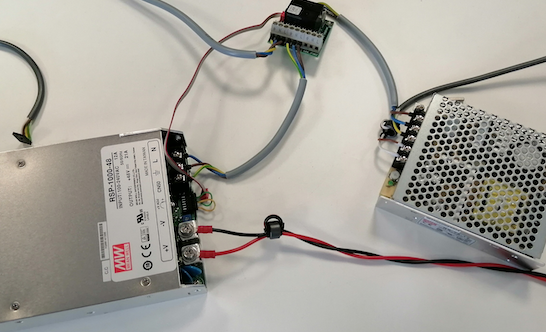
H) A safety relay and two power supply units (PSUs) identified, one for the compute logic (12V) and another one to power the actuators (48V).
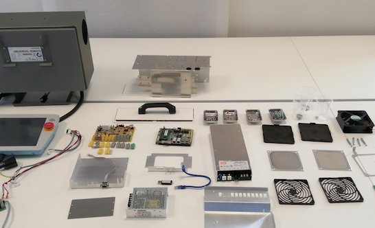
I) Final figure depicting all the components contained inside of the Universal Robots UR3 CB3.1 controller, leaving aside the teach pendant.
Suitability for use — NXP Semiconductors products are not designed, authorized or warranted to be suitable for use in life support, life-critical or safety-critical systems or equipment, nor in applications where failure or malfunction of an NXP Semiconductors product can reasonably be expected to result in personal injury, death or severe property or environmental damage. NXP Semiconductors and its suppliers accept no liability for inclusion and/or use of NXP Semiconductors products in such equipment or applications and therefore such inclusion and/or use is at the customer’s own risk.
In other words, this observation leads us to question the quality and reliability of the safety implementation within robots of the CB-Series from Universal Robots. Our research
3.22.2 Case Study 2: Teardown of a next-gen industrial collaborative robot
Following the CB-Series, we proceeded and disassembled one of the latest releases from Universal Robots, the UR3e, an e-Series. Figure 3 depicts the complete process through selected images.
We observe how while the overall outer look remains similar, the internals have suffered a significant change:
- The e-Series controller integrates a single PSU, as presented in Figure 3E, while the CB-Series had two (see Figure 2H).
- While the CB-Series presented two boards containing compute, power, and safety logic (Figures 2C and 2F, respectively), the e-Series presents only one single PCB board named as “SAFETYCONTROLBOARD” and depicted in Figures 3F, 3G, 3H and 3I.
- Figure 3G shows that the new PCB includes a Xilinx Artix-7 series field-programmable gate arrays (FPGAs), widely used for implementing safety logic in a variety of automotive and control domains, and a much more reliable compute substrate for safety-related tasks than a MCU.
- Figure 3J shows that the base filter PCB—which helps interface power and RS485 communications from the controller (e-Series) to the robot arm mechanics—is similar to the one present in the CB-Series. We also note that, while the arm mechanics connector changed in the e-Series (see Figure 3K), power and communications lines remain coherent (through the base filter board).
- For the most part, the electronics contained in the arm mechanics (see Figure 3L) do not present relevant changes from an interoperability perspective. This facilitates re-purposing and reusing them (see Section 3).
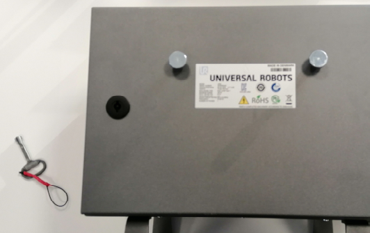
A) Universal Robots UR3e controller. The controller has a mechanical lock aimed to prevent ingress to the internals from non-authorized parties.
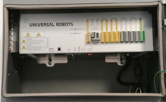
B) Inside the controller we can see various connectors and cables exposed. The right side includes I/O and safety, at the bottom USB, HMI and SD card.
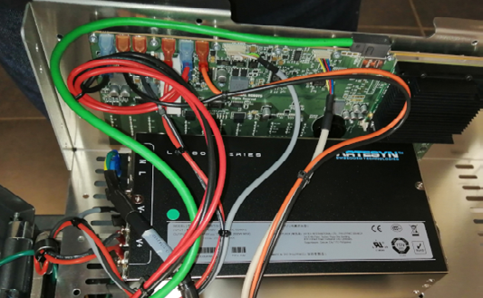
C) The main computer of the controller and the PSU are affixed to the front plate. Given the real state available we miss some cable management.
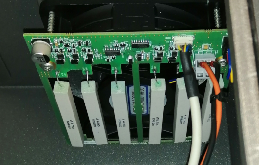
D) The energy-eater board. This component tends to overheat a fair bit and should generally be checked in case of failure for signs of degradation.
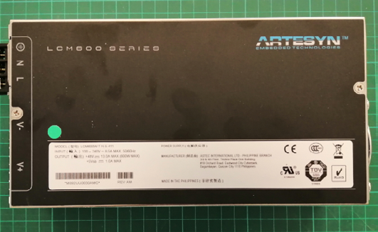
E) The PSU is a Artesyn LCM600 series with an output of 48 V, and an input of 85–264 Vac. Has a typical full load efficiency of 89% up to 600 watts.
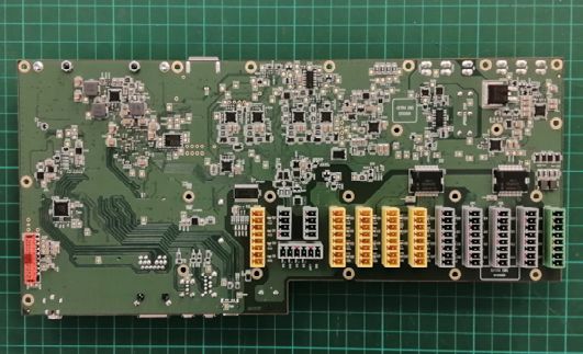
F) Unlike previous hardware iterations, the e-Series controller presents both the safety logic and the control logic merged into a single PCB. See Figure 6 for a simplified diagram.
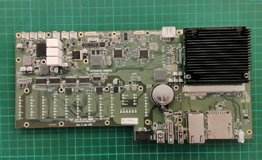
G) DC to DC power management takes place on the board unlike previous iterations. The positions of the relays may hinder transistor cooling.
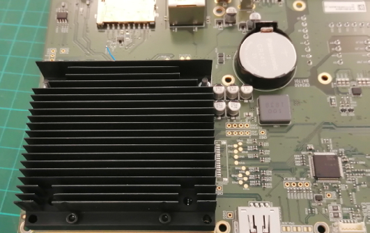
H) Under the heatsink we find a MSC Q7-BT module on an ECX form factor and an Intel SoC with DDR3L memory.
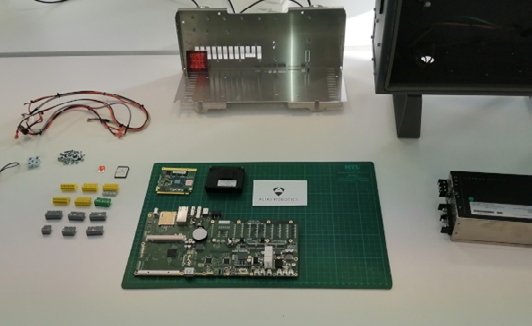
I) Final figure depicting all the components contained inside of the Universal Robots UR3e controller, leaving aside the teach pendant.
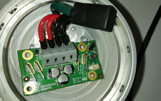
J) Opening the base joint of the manipulator we find the connections coming from the controller, the 48V leads and the micro-USB for data.
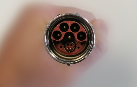
K) Even though the pin-out is quite similar to previous iterations of the CB3 controller, the connector itself has a different shape.
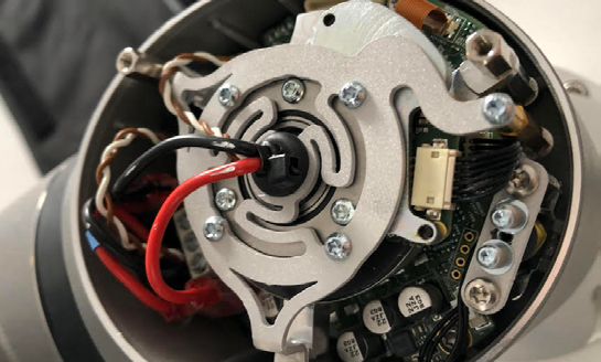
L) Opening a joint we find the harmonic drive, on top of the PCB for communication and power distribution. And the release solenoid.
Looking at the results of our teardown, we highlight the following observations.
3.32.3 Case Study 3: Teardown of a mobile industrial robot
Figure 4 depicts the teardown process of a MiR-100, a popular mobile robot manufactured by the Danish Mobile Industrial Robots (MiR), also owned by the US Teradyne. The first impression is that various components of the robot could be improved from a safety perspective, as highlighted in Figure 4G or 4I. Moreover, the teardown helped understand how this robot presents multiple (internal and external) networks and how each one of the sensors and actuators are connected across these networks, forming the data layer graph. One interesting finding resulting from the teardown is obtaining a better understanding of the robot’s computational graph (the behavior itself). The robot itself is powered by Robot Operating System (ROS)
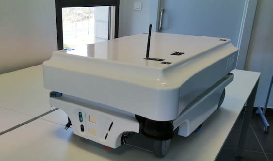
A) The top shell sits on top of a metal frame that protects all the electronic components. Simply lifting the top shell reveals the internal electronic components.
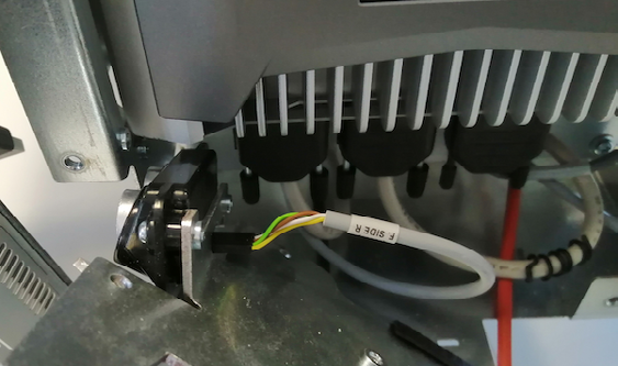
B) A circuit-breaker switch is present to disconnect the main power line going from the batteries to the rest of the robot. A quick-release connector is also present.
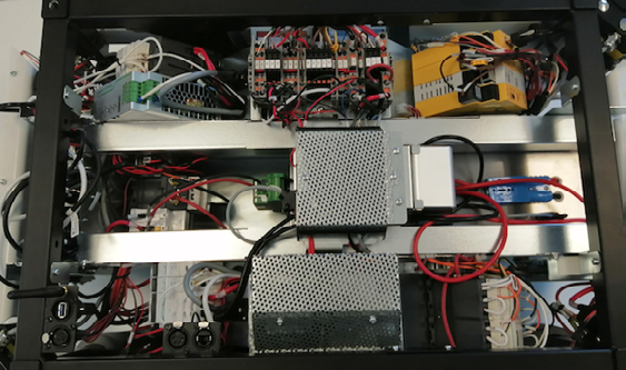
C) Plastic fenders are identified around the perimeter of the mobile robot to enclose and protect the internals. These are prone to crack under heavy mechanical stress.
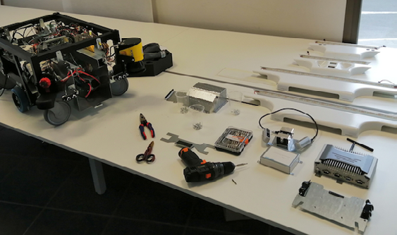
D) The battery is enclosed in a steel box and held by a retaining plate to prevent movement and connected to a DP9 connector and DC 24V wires.
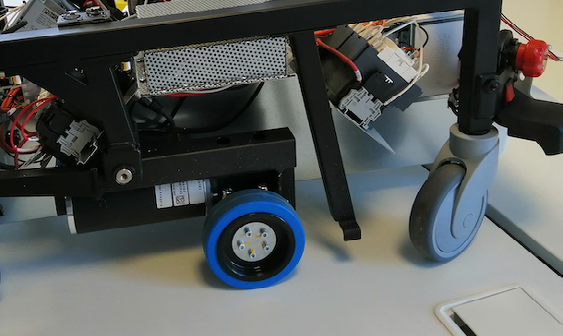
E) Under an RF cage we find a Teensy board for LED control and a third party speaker to play the sounds from the on-board controller.
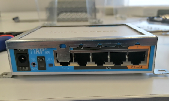
F) Under an RF cage we find a Teensy board for LED control and a third party speaker to play the sounds from the on-board controller.
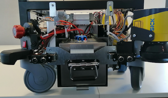
G) The on-board controller is the embedded and “ruggedized” EC70A-SU from DFI which features an Intel processor and a Ubuntu 16.04 file system.
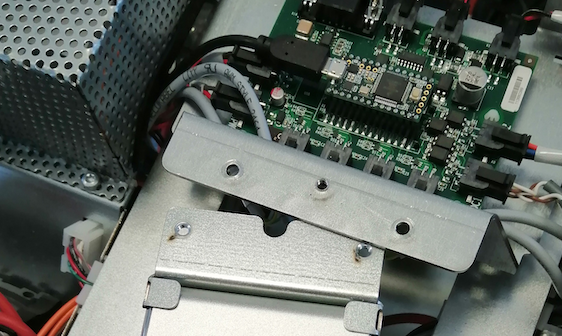
H) Final figure depicting the main components contained inside of the MiR100 robot, alongside the tools used for the teardown.
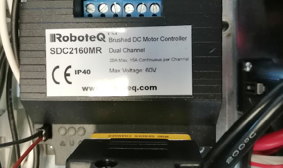
I) Both the safety programmable logic controller (PLC) and the on-board controller are connected to a Mikrotik hAP ac. A 2.4/5GHz dual-band omnidirectional access point.
43. Teardown-enabled security research
The previous section highlighted how teardown helped identify quality and safety issues in robots, as well as obtaining a better understanding of their architectures by matching each robot’s data layer graph with their corresponding computational graph. Beyond this, we argue that robot teardown is also key for security research in robotics. Recall that safety and cybersecurity are very related and influence one another
Teardown, as a process, is an essential part of a hardware reverse engineering task, and brings useful lessons and insights for the design of current and future robot systems. Generally, teardown supports Kerckhoffs’ principle in revealing all the details and weaknesses of a security system, excluding volatile secrets such as keys or credentials that are stored in memory and most likely disappear naturally once the power supply is taken away (with the exception of keys stored in permanent memory, which is generally discouraged, and would be discovered along the teardown process). Overall, the history of proprietary systems violating Kerckhoffs’ principle by pursuing security-by-obscurity is rich of failure cases (with the military domain as the sole exception), as a vast amount of related work demonstrates.
Reverse engineering has always been invaluable to discover vulnerabilities and develop remedies in many domains: network security
Particularly, and as part of this research, our group identified more than 100 security flaws across the three robots described above over a period of two years. Most of the flaws were cataloged as vulnerabilities and 17 obtained new CVE IDs all of which was publicly disclosed at the Robot Vulnerability Database (RVD)
We advocate for robot teardowns as a means to improve security in robotics and encourage manufacturers, integrators and end-users to carefully consider the underlying hardware architecture to protect their robotic systems. Similarly, we encourage teardowns as a tool to mitigate outstanding security flaws. Proper knowledge of the hardware helps determine which additional elements can help mitigate security issues when the manufacturer does not react. As an example, our group introduced an additional commercial off-the-shelf hardware firewall within MiR’s internal network between the main controller and the SICK’s safety PLC mitigating RVD#2558 without having to modify any parts of the firmware. This modification could enable users and system integrators frustrated with MiR’s security policies to secure their robots directly.
| CVE ID | RVD ID | Description | Report |
|---|---|---|---|
| CVE-2019-19626 | RVD#1408 | Bash scripts (magic UR files) get launched automatically with root privileges and without validation or sanitizing | https://github.com/aliasrobotics/RVD/issues/1408 |
| CVE-2020-10290 | RVD#1495 | Universal Robots URCaps execute with unbounded privileges | https://github.com/aliasrobotics/RVD/issues/1495 |
| CVE-2020-10267 | RVD#1489 | Unprotected intelectual property in Universal Robots controller CB 3.1 across firmware versions | https://github.com/aliasrobotics/RVD/issues/1489 |
| CVE-2020-10266 | RVD#1487 | No integrity checks on UR+ platform artifacts when installed in the robot | https://github.com/aliasrobotics/RVD/issues/1487 |
| CVE-2020-10265 | RVD#1443 | UR dashboard server enables unauthenticated remote control of core robot functions | https://github.com/aliasrobotics/RVD/issues/1443 |
| CVE-2020-10264 | RVD#1444 | RTDE Interface allows unauthenticated reading of robot data and unauthenticated writing of registers and outputs | https://github.com/aliasrobotics/RVD/issues/1444 |
| CVE-2020-10278 | RVD#2561 | Unprotected BIOS allows user to boot from live OS image | https://github.com/aliasrobotics/RVD/issues/2561 |
| CVE-2020-10270 | RVD#2557 | Hardcoded Credentials on MiRX00 Control Dashboard | https://github.com/aliasrobotics/RVD/issues/2557 |
| CVE-2020-10279 | RVD#2569 | Insecure operating system defaults in MiR robots | https://github.com/aliasrobotics/RVD/issues/2569 |
| CVE-2020-10276 | RVD#2558 | Default credentials on SICK PLC allows disabling safety features | https://github.com/aliasrobotics/RVD/issues/2558 |
| CVE-2020-10273 | RVD#2560 | Unprotected intellectual property in Mobile Industrial Robots (MiR) controllers | https://github.com/aliasrobotics/RVD/issues/2560 |
| CVE-2020-10277 | RVD#2562 | Booting from a live image leads to exfiltration of sensible information and privilege escalation | https://github.com/aliasrobotics/RVD/issues/2566 |
| CVE-2020-10269 | RVD#2566 | Hardcoded Credentials on MiRX00 wireless Access Point | https://github.com/aliasrobotics/RVD/issues/2566 |
| CVE-2020-10275 | RVD#2565 | Weak token generation for the REST API | https://github.com/aliasrobotics/RVD/issues/2565 |
| CVE-2020-10274 | RVD#2556 | MiR REST API allows for data exfiltration by unauthorized attackers (e.g. indoor maps) | https://github.com/aliasrobotics/RVD/issues/2555 |
| CVE-2020-10271 | RVD#2555 | MiR ROS computational graph is exposed to all network interfaces, including poorly secured wireless networks and open wired ones | https://github.com/aliasrobotics/RVD/issues/2555 |
| CVE-2020-10272 | RVD#2554 | MiR ROS computational graph presents no authentication mechanisms | https://github.com/aliasrobotics/RVD/issues/2554 |
54. Finding and bypassing planned obsolescence in robotics
One of the results of the teardown case studies described in Section 2, our group identified several of the planned obsolescence indicators introduced in Section 1. Planned obsolescence was particularly evident in the robots from Universal Robots. To further illustrate this, Figure 6A and 6B depict the simplified electrical diagrams of the UR3 and UR3e robots. From an electrical point of view, these two robots present a similar layout for interfacing with the robot arm.
While we appreciate certain changes in the electronics, given the teardown results, we find no real reason why backwards or forward compatibility between controllers and robotic arms should not be possible. This would mean that existing customers with UR3 robots could repair and replace parts in either the controller or the robotic arm, without being forced to pay the premium price of buying a complete new set including both.
Unsurprisingly, we observe that the manufacturer introduced subtle changes meant to make this particular intent harder. One of such actions is depicted in Figure 3K, which shows the replacement of the controller-to-arm connector, which we can only justify with attempts to exercise obsolescence practices. Another of such actions includes the obscurity around the changes introduced in the UR3e robot arm itself. These changes can be summarized with the addition of an extra 6-axis force-torque sensor at the end of the robot. The exact same result can be achieved in UR3 robot arms by adding commercial off-the-shelf robot components, gaining such capabilities.
As a result of the previous teardown efforts, the following sections describe some of the actions that could be performed to bypass planned obsolescence practices identified.
5.14.1 controllerAdapter: UR3 controller with UR3e mechanics, and the other way around
As depicted in Figure 6, both UR3 and UR3e are electrically coherent when it comes to the interfaces between their respective controllers and robotic arms. By adapting the corresponding connector (first depicted in Figure 3K), we manage to electrically enable interoperability between UR3 and UR3e controllers and robotic arms. This is further illustrated in Figure 5 as controllerAdapter.
Two controllerAdapters where produced using off-the-shelf male/female connectors for a total BOM price under 20 Euros. This allowed to match both power lines and communication bus lines across all UR3 and UR3e possible combinations.
5.24.2 armAdapter – Drive UR3 without controller
The RS485 communication bus lines used to interface with the robot arms (both UR3 and UR3e) are propagated from the controller down to the tip of the arm, the tool mounting bracket. This is highlighted with brown and yellow lines in Figure 5. While artificially maintaining an external power supply through the power lines coming from the controller, we prototyped the complete removal of the UR3e controller successfully. Instead of the default controller, we used a Raspberry Pi single board computer and some minor additional electronics to drive the arm. These get connected to the tool mounting bracket which exposes both the power lines and the RS485 communication bus lines. Simple movements were achieved by replaying the underlying Modbus TCP protocol commands obtained by both inspecting public documentation and wiretaping the bus with a logic analyzer.
We called this second prototype armAdapter and while we discourage its use in production environments (since it lacks completely of any safety considerations), it demonstrates how teardown empowered research allows to extend the robot capabilities and bypass the obsolescence hardware limitations, obtaining full control of the hardware across both UR3 and UR3e releases.
Note that the yellow lines in the diagram are in fact white in the real robot as illustrated in Figure 3L.
65. Conclusions
In this article we presented robot teardowns as an approach to study robot hardware architectures, obtain repairing capabilities and research its security. We discuss the empirical results of three robot teardowns and the findings affecting quality and safety throughout the process. We then discuss how teardown is a relevant tool for security research in robotics which helps pinpoint security flaws early across the multiple internal and external networks in a robot. Moreover, we introduce our security findings and propose mitigations powered by the hardware know-how and repairing capabilities acquired. Ultimately, we research planned obsolescence practices in the robots from Teradyne and propose actions that could be taken to bypass obsolescence.
Our results show evidence that robot teardowns can help the robotics industry and supply chain by improving significantly quality, safety and security. Our findings extrapolate to most of the robots manufactured by Teradyne and its subsidiaries. We show concern for the currently growing trend in robotics to create private networks of certified groups, a common practice shown by manufacturers like MiR or UR, both owned by Teradyne. This difficulties system integration, repairability and ultimately security. We advocate for a ‘Right to Repair’ in robotics and encourage end-users to reflect their needs into their supply chains and into the original upstream robot manufacturers.
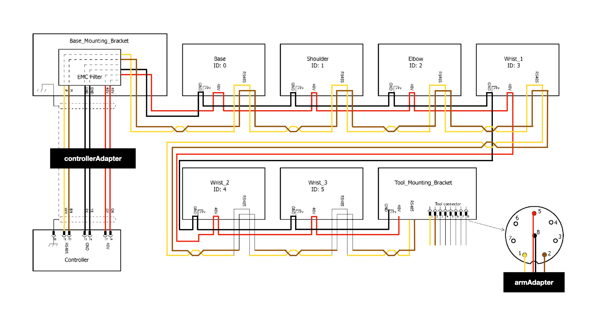
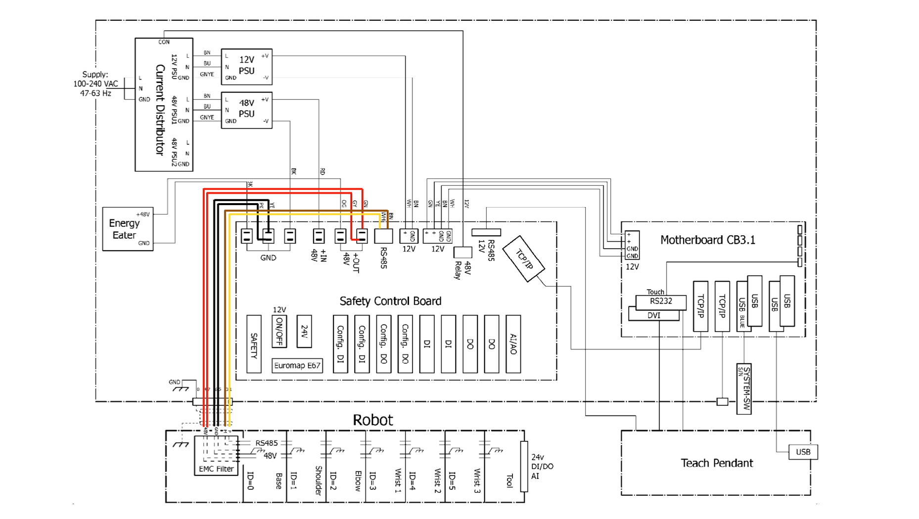
A) Simplified electrical diagram of Universal Robots UR3 CB-Series collaborative robot.
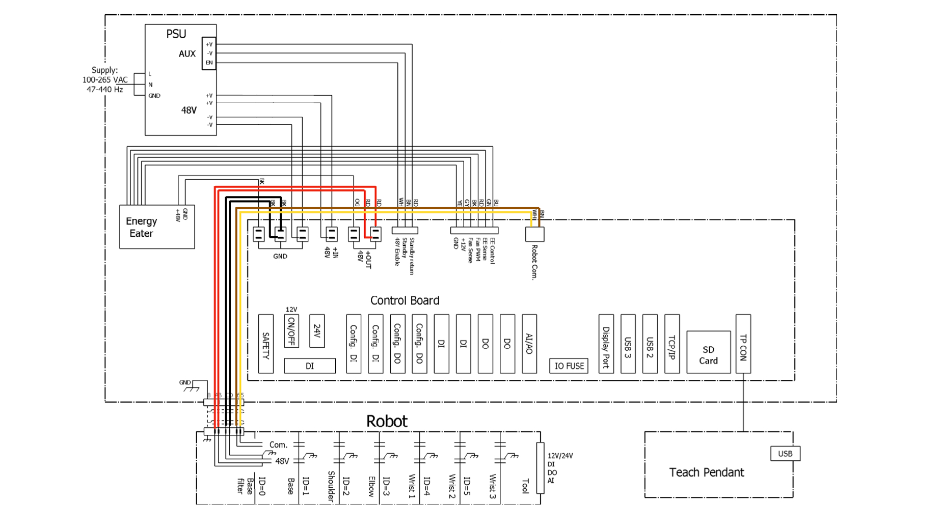
B) Simplified electrical diagram of Universal Robots UR3 CB-Series collaborative robot.
7Declaration of Conflicting Interest
The author(s) declared no potential conflicts of interest with respect to the research, authorship, and/or publication of this article.